The following section describes design guidance for non-injector Bayer in Radiology devices. The guidance is intended to provide examples of the ‘accessory’ devices and design approaches which can be adopted for them.
For general design approach, principles and guidelines when designing accessories, refer:
Note: Only guidance specific to an accessory device type, or hold exceptions to the referenced guidance above are outlined in following sections.
Workstations
Workstations enable interconnectivity between image scanners, injectors and databases/information services. Often purchased with a Radiology injector device, it is connected to allow for control of an injector from the control room.
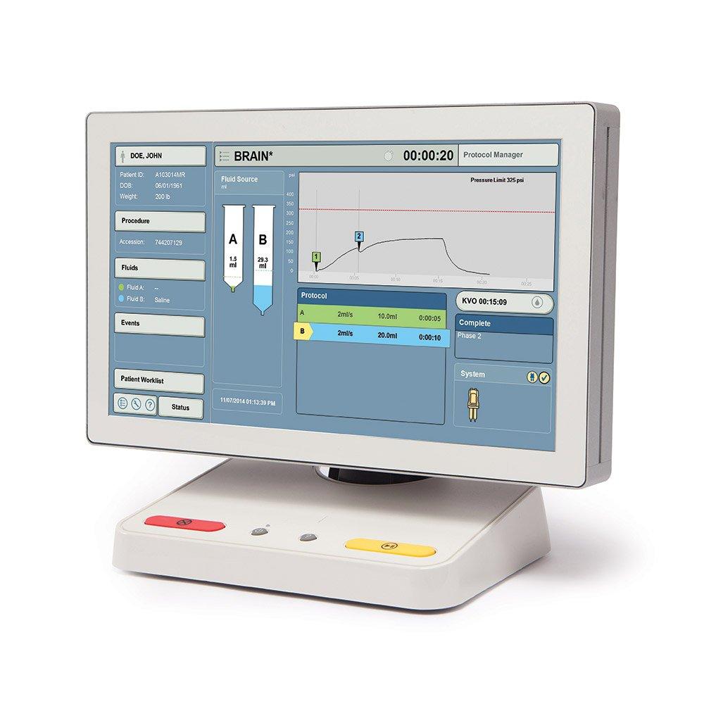
Use & Environment
Used in control rooms outside of the imaging room, are typically amongst other displays and user interfaces on a desktop.
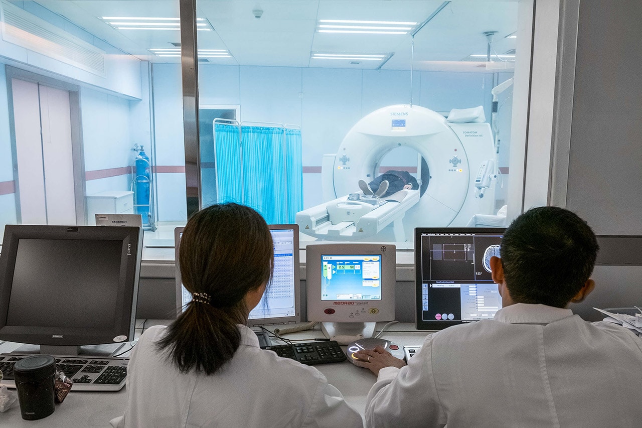
Space can be a premium, it is not atypical the room is small, desks can be somewhat cluttered in which the workstation may be competing for physical space and presence.
Lighting in control rooms can also range widely from bright to dark.
General guidance:
As such, when designing a workstation device, consider:
- The control room environment & parallel devices around it.
- Where possible, reduce the over footprint/size of the design.
- Controls should be visible in both dark and bright environments.
- Visual consistency with Bayer in Radiology injector devices.
Workstation: Workstation 3

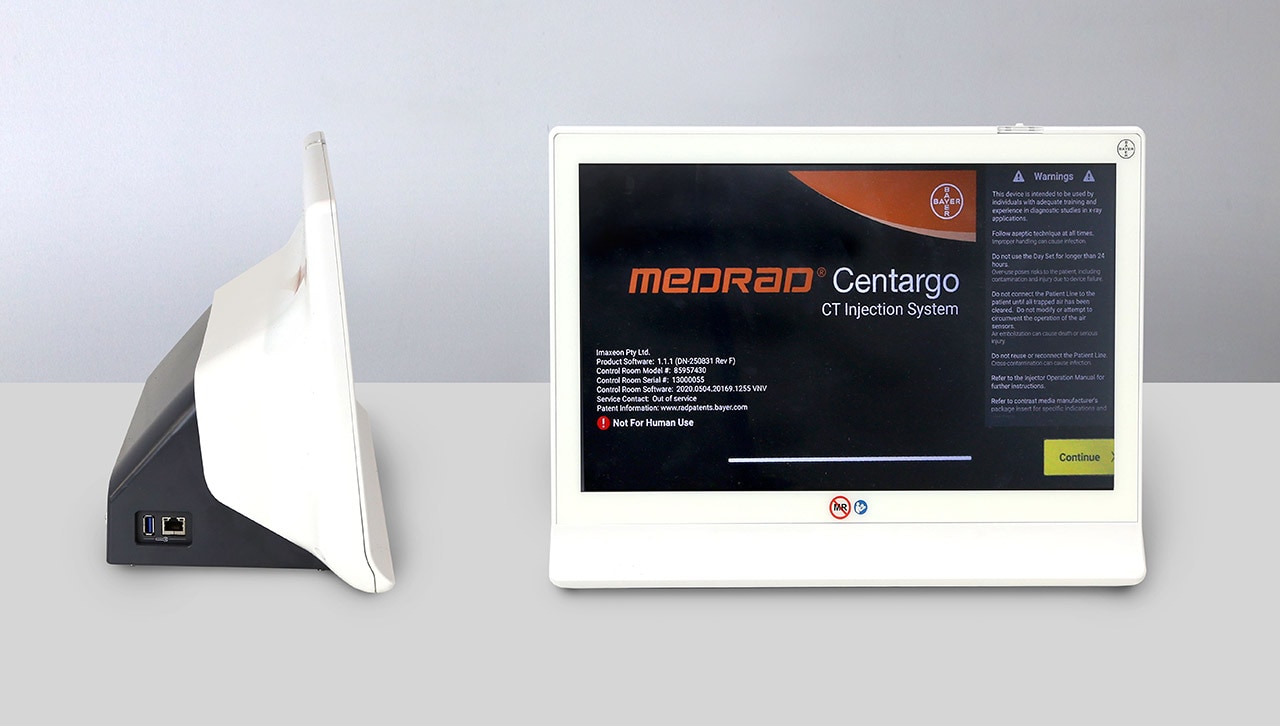
- Adopt simple geometric forms to minimize visual clutter. Here from the front, a simple rectangular form is adopted to frame the touch screen.
- The color pallet follows guidance as per the Hardware Color guidance: White as the primary color and Dark Grey for the base to minimize visual volume and ‘bulk’ of the base.
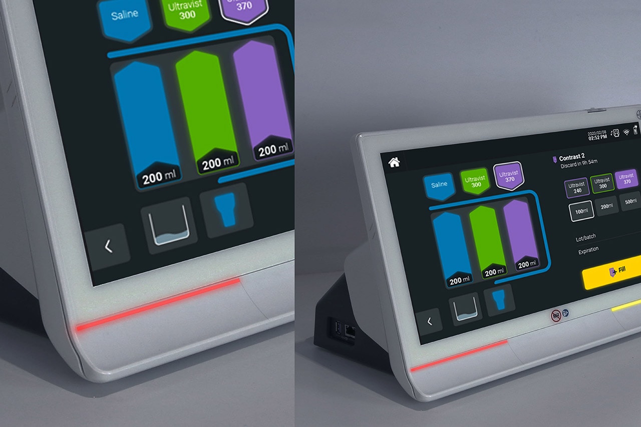
- Physical buttons are illuminated for visibility in dark environments.
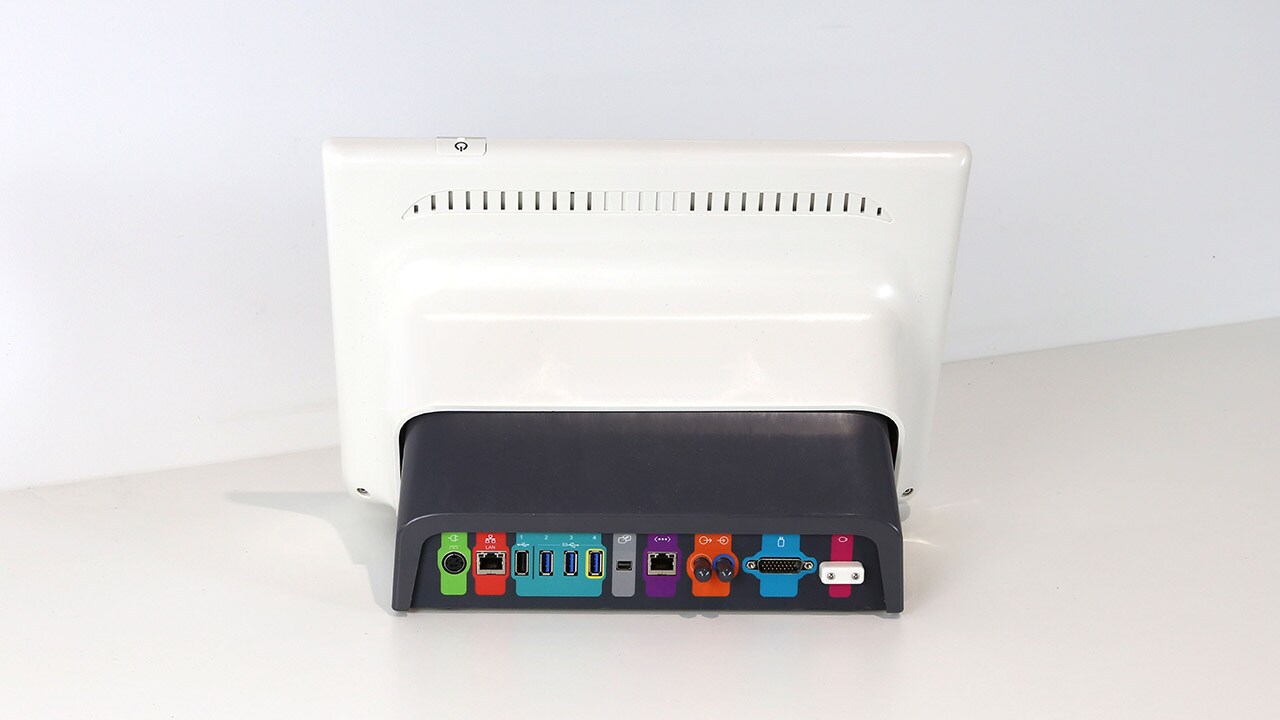
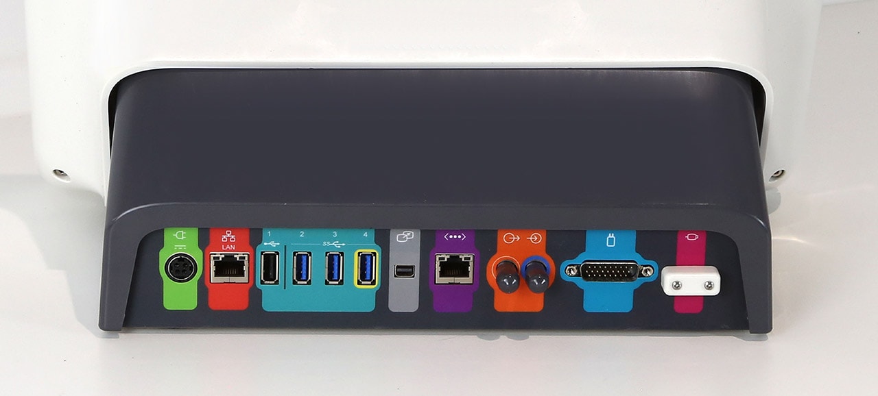
- Device ports located at rear of device, following a Device Communication Port Color system. Refer:
Hub Devices
Hub devices enable interconnectivity between image scanners, injectors and databases/ information services.
However, unlike a workstation device there is no integrated touch screen. Users connect to it via third party display screens and mobile devices (wired and wirelessly). This allows users alternative workflow/ setup options, where mobile devices are used, enables access to the connected devices whilst mobile.
Use & Environment
Hub devices are either in imaging and control rooms and are typically placed out of the way and somewhere discrete.
They can be rarely interacted with once the device is set up, thus visual feedback and device status is important with the absence of a screen to interact with.
As common with hardware with processing, the electronics may create heat that require dissipation to prevent overheating. In this case, venting features maybe required.
General guidance:
When designing a Hub device, consider:
- Visual feedback/status indicators which is sufficiently visible in both dark and bright environments.
- Venting features which are not over embellished and that adopts simple geometric forms that align with the hardware shapes, forms & surfaces guidance.
Hub Device: Bayer Workflow Hub
- The top profile shape of the device is simple and clean, side surfaces are treated with concave curvature to add interest and dynamism.
- White as the primary color and Light Grey. This visually breaks up surfaces and the device volume.
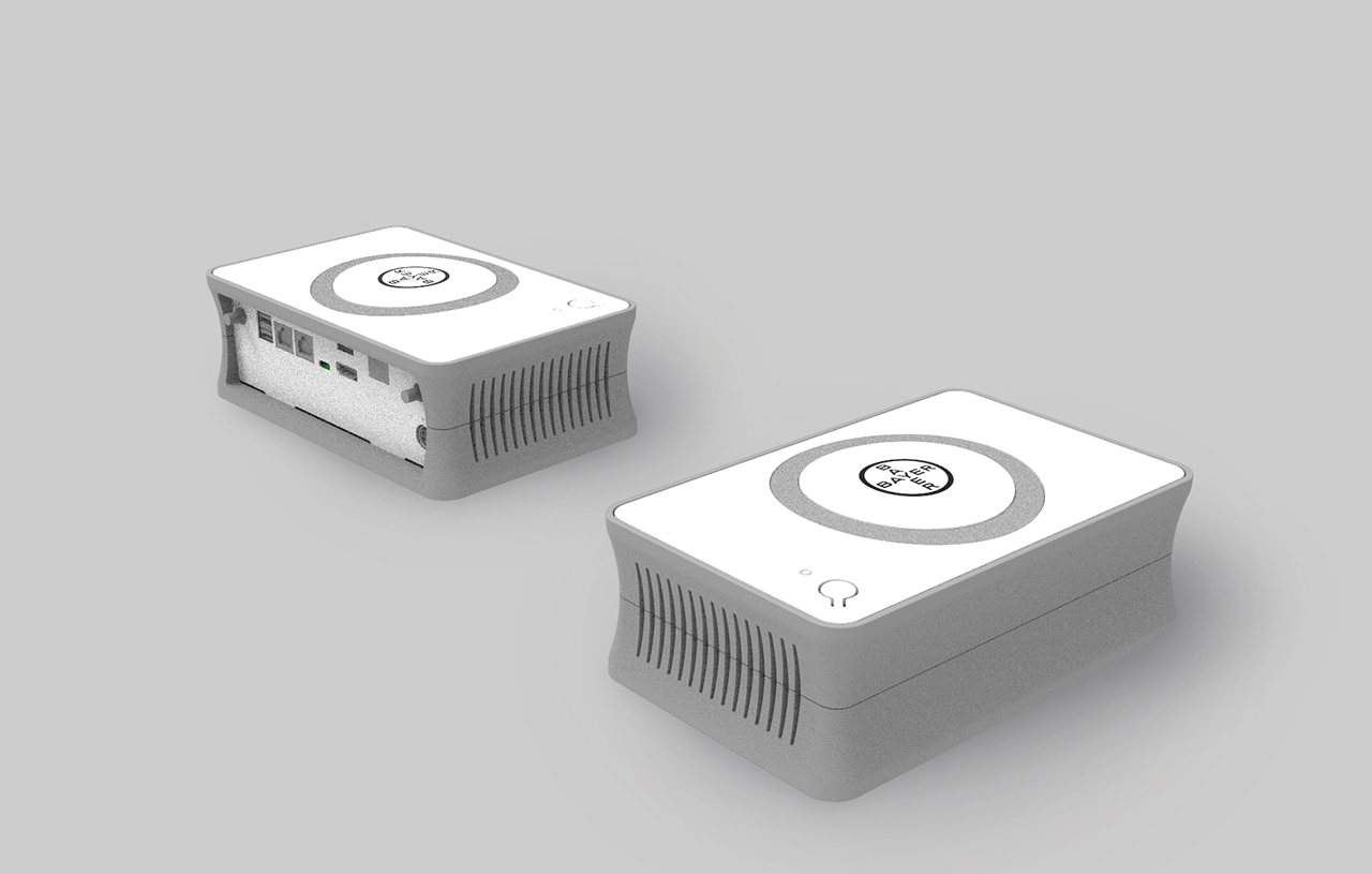

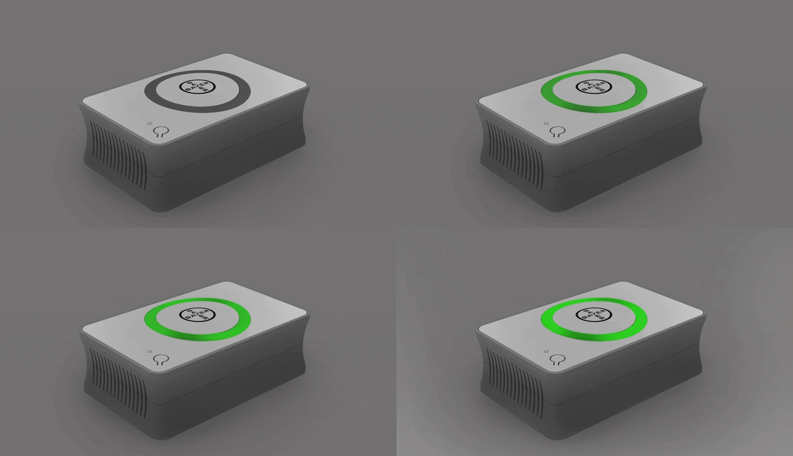
- The unit integrates a LED ring light pipe to indicate device status:
Power On Status Green
Connected Status White light, On – Off
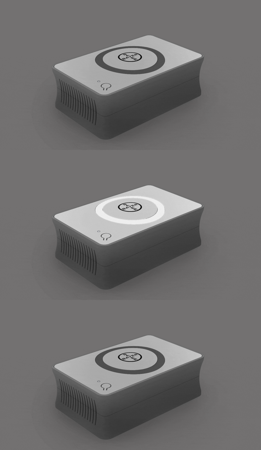
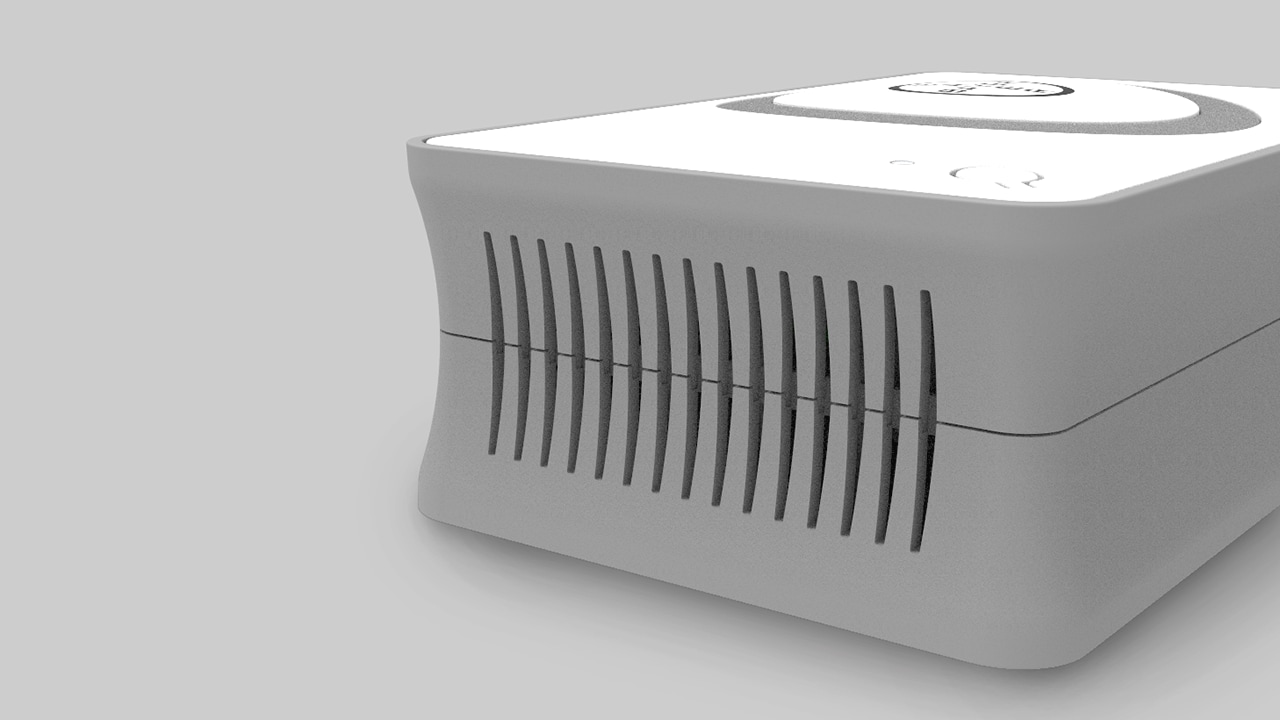
- Vent geometry with simple long ‘pill shapes’ in repetition.
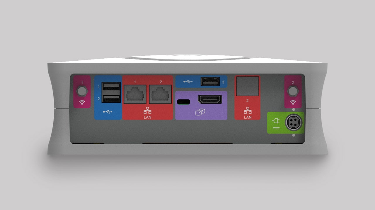
- Device ports located at rear of device, following a Device Communication Port Color system.
Barcode Readers
Barcode readers (and other peripheral devices) are sometimes integrated into injector devices to scan consumables such as sterile disposables and injection fluids.
They typically can be fully integrated (concealed) or attached to the device externally, intended to be held by the user during use offering alternate workflows.
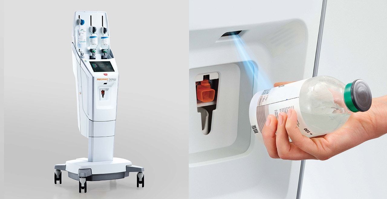
When integrating a barcode reader that is concealed, consider:
- Simple Sufficient visual cues to indicate the location of the reader
When designing a handheld barcode reader, consider:
- Visual consistency and relationship with the radiology device it is to be integrated with as far as Form, shape, color and materials/finishes.
- The same guideline above applies for any off the shelf reader sourced for integration with the radiology device.
Device Controllers
Device controllers are sometimes integrated into injector devices to allow precision control of fluid delivery in addition, offering an alternative input method for hardware control.
The following section shows examples of Bayer in Radiology controllers.
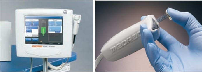
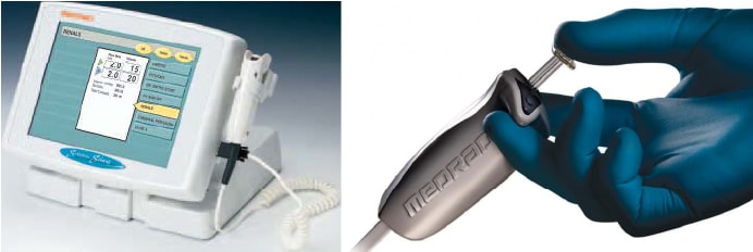
When designing a hand controller, consider:
- Visual consistency and relationship with the radiology device it is to be integrated with as far as Form, shape, color and materials/finishes.
Device Port Labels
Device labels identify connection ports and cable types for device hardware. Colors, logos and styles used should be applied consistently and standardized across hardware devices.

The following section outlines the applied color system and logos adopted to connection port and cable types typical of a Bayer in Radiology hardware device.
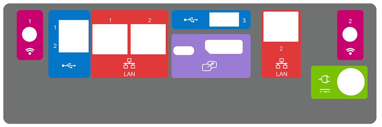
Connection Port Label Specifications

| Icon | Function/Port | Color | CMYK |
|---|---|---|---|
| WIFI | Dark Pink | 18,100,25,0 | |
 |
USB | Blue | 84,49,0,0 |
 |
LAN | Red | 5,95,89,0 |
 |
Screen Extension |
Lilac | 3,54,0,0 |
| Power | Lime Green | 57,0,100,0 | |
 |
Fiber Optic Input/Output Terminal |
Orange | 4,73,100,0 |
 |
Injector Head | Teal | 78,24,24,0 |
| Hand-switch | Pink | 19,100,14,0 | |
| Service | Gray | 63,56,53,28 |
If you have any further questions about this or any other section of Bayer Identity Net, please contact:


